
| Agricultural Drainage Pipe Detection |

|
Agricultural Drainage Pipe Detection
Using Ground Penetrating Radar
Summary: Enhancing the efficiency of soil water removal, and in turn crop productivity, on land already containing an agricultural subsurface drainage system, typically involves installing new drain lines between the old ones. However, before this approach can be attempted, the older drainage pipes need to be located. A research investigation has foundthat ground penetrating radar (GPR) was successful in locating on average 72% of the total amount of pipe present at thirteen test plots in southwest, central, and northwest Ohio. This method was successful in finding clay tile and corrugated plastic tubing drainage pipe down to depths of around 1 m (3 ft).within a variety of different soil materials. Additional research has focused on determining the impact that equipment parameters, site conditions, field operations, and computer processing have on GPR drainage pipe detection. Results with respect to equipment parameters indicate that choosing the proper antenna frequency is crucial, and antennas with a center frequency of around 250 MHz seem to work best. Also, data quality is similar over a substantial range of spatial sampling intervals and signal trace stacking. In regard to the site conditions, shallow hydrology, soil texture, and drainage pipe orientation all influence the GPR response. Likewise, field operations (measurement line spacing and bi-directional surveys) along with the algorithms used in the computer processing sequence are very important considerations. The information obtained in this study can hopefully be used to develop guidelines that will enhance the potential for success of using ground penetrating radar to locate buried agricultural drainage pipe.
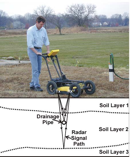
This schematic illustrates how ground penetrating radar (GPR) equipment is used to locate buried agricultural drainage pipes. The principle of the GPR method involves directing an electromagnetic radio energy (radar) pulse into the subsurface, followed by measurement of the elapsed time taken by the signal as it is travels downwards from the transmitting antenna, partially reflects off a buried feature, and is returned to the surface, where it is picked up by a receiving antenna.

The preceding figures depict some typical ground penetrating radar (GPR) results with regard to locating buried agricultural drainage pipe. Figure a and Figure b are GPR generated images of the soil profile. As shown in these profiles, the GPR response to different buried drainage pipe orientations range from upside-down U-shaped to distinct linear banded features. Figure c is a map depicting the relative radar energy reflected back to the surface from a depth interval of 0.9 to 1.4 meters. Lighter shades on the map indicate greater reflected radar energy. Lightly shaded or white linear features often represent drainage pipes. Figure d is an interpreted map based on the GPR data showing the drainage pipe system with dashed lines. The blue line on Figure d indicates the line position along which the Figure a GPR profile data were collected. The red line on Figure d indicates the line position along which the Figure b GPR profile data were collected.

This GPR profile from data collected along trend directly over top of a drainage pipe in saturated soil shows the abrupt transition from a water-filled pipe (west side) to an a air-filled (east side). This abrupt transition in the GPR response is due to a pipe obstruction that completely blocks the flow of water.
Contact Information:
Barry J. Allred
USDA/ARS - Soil Drainage Research Unit
590 Woody Hayes Drive, RM. 234
Columbus, Ohio 43210
Phone: 614-292-9806
Fax: 614-292-9448
E-mail: barry.allred@ars.usda.gov